./ 2022
Macro Deck
A handcrafted macro deck for those who prefer tactile shortcuts
Details
- Tools
- Team
Leonardo Mussatto
./ introduction
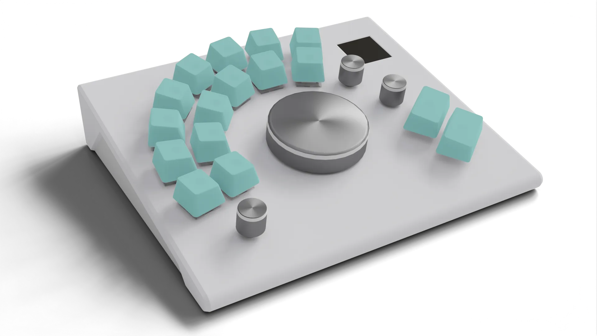
Macro Wheel is a self-initiated hardware project: a compact, programmable macro deck designed to streamline shortcut-heavy workflows across creative software. It’s both a personal productivity tool and a full-stack learning exercise - from PCB design and firmware to case prototyping and desktop companion UI.
The device merges mechanical key switches, rotary encoders, addressable LEDs and a 1.3-inch TFT display into a small desktop controller that connects via USB and acts as a native HID keyboard. A companion app (written in AutoHotkey with a Neutron-based UI) manages profiles, LED states and automatic switching based on the active program.
The project is a work in progress - functional hardware is assembled, firmware and UI are under development, and the case design needs a revised print.
./ development
Intent
Macro Wheel sits at the intersection between a practical productivity tool and a learning-driven hardware project. While similar control surfaces already exist, this prototype was conceived primarily as a way to understand — through practice — how such devices are designed, built and integrated into everyday creative workflows.
Spending long hours in tools like Blender, DaVinci Resolve or TouchDesigner involves constant use of keyboard shortcuts and frequent switching between input devices. Designing and building a macro deck from scratch provided a concrete way to examine how part of this cognitive and physical load can be offloaded onto a customisable, context-aware physical interface.
Beyond its immediate usefulness, the project functioned as an end-to-end exploration: from PCB layout and firmware architecture to mechanical tolerances and desktop automation. The result is a working device that supports real tasks, but whose primary value lies in the understanding gained through its design and construction — including the trade-offs that shape specialised tools of this kind.
Firmware
Developed in PlatformIO (VS Code) using:
- Arduino Keyboard / HID libraries for native HID keystroke output.
- Adafruit MCP23X17 and MCP23X08 libraries.
- Modified MD_REncoder library to support encoders connected through MCP devices.
- Custom interrupt and event-handling code for encoders and matrix inputs.
Each input emits a unique HID key combination (F13–F24 with modifiers). These keystrokes are intercepted by the companion script, which maps them to user-defined actions.
Firmware for LEDs and the display is pending implementation; current focus is on stabilising the encoder and switch logic.
Companion Script and UI
Written in AutoHotkey (AHK) with a Neutron HTML/CSS interface, the desktop companion:
- Loads and saves profiles via a human-readable
.inifile (import/export supported). - Lets users assign macros, media or mouse actions to each input.
- Will (in later builds) manage LED colour and automatic profile switching based on the foreground application.
At runtime, the companion listens for HID inputs (F13–F24 + modifiers), then triggers the mapped actions. This architecture keeps the firmware simple and light while allowing customization and process aware logic. Being written in AHK, it currently only supports Windows.
- Loads and saves profiles via a human-readable
Design & Fabrication
3d printed as a prototype, the next iteration will correct angles, add encoder wheels, and fit the display.
- PLA case: mechanical testing revealed that the rear angle was too shallow, making PCB insertion difficult once encoders were soldered.
- Display fit: the TFT module did not align and fit inside the first print - future revision increases clearance.
- Side panels: frost acrylic (CNC-milled by the university workshop technician).
- Mounting: PCB fixed with screws to the PLA bottom.
./ roadmap
Next Steps
- Revise and reprint case (correct rear angle, LCD fit, encoder wheels).
- Finish soldering LEDs + display.
- Extend firmware with LED profiles and display UI.
- Complete companion UI (LED editor, auto-switching).
- Documentation: improve document and update open-source repository